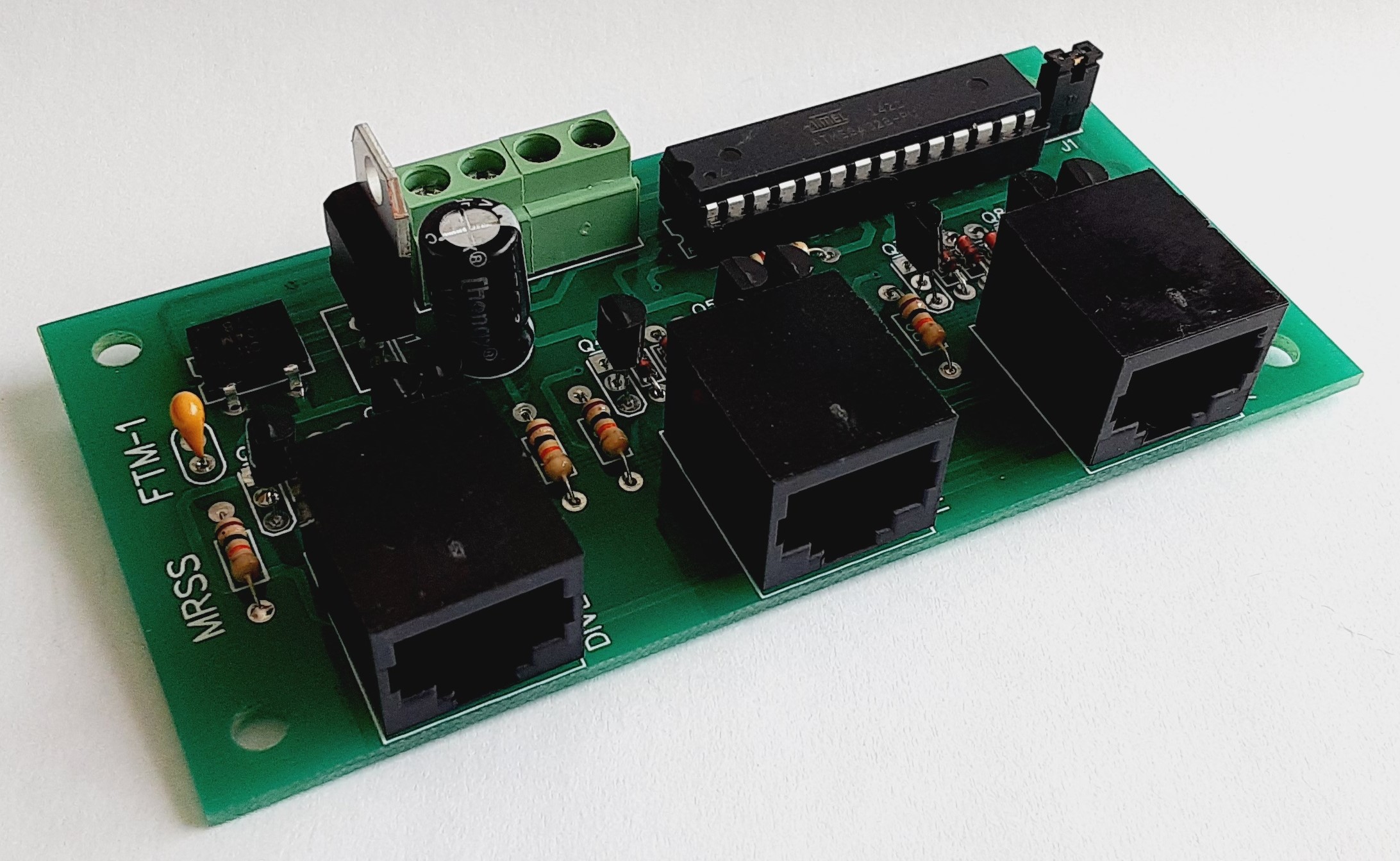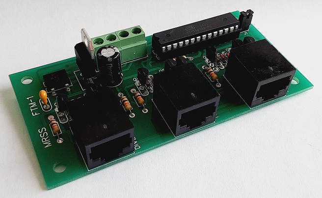

FTM-1 Description
.:
The FTM-1 has been designed to route occupancy bus information from one route to another. This is accomplished by monitoring the position of the turnout and routing the signal information in the proper direction. The path that is not selected receives a stop signal while the selected route displays the appropriate aspect based on the occupancy status of the blocks surrounding the turnout.
This particular turnout module simply routes the signal information and is designed to be used in locations where signals are not required at the turnout.
The FTM-1 board can operate in two different modes. Mode one allows for signal information to be repeated. For example, a STOP signal on the input will produce a STOP aspect on the output. An APPROACH signal on the input will produce an APPROACH aspect on the output. This is useful when the turnout is located in the middle of a protected section of track or block.
Mode two works the same as a cascade module. A STOP signal on the input will produce an APPROACH aspect on the output. An APPROACH signal on the input will produce an ADVANCE APPROACH aspect on the output. This mode is meant to be used when a turnout is located at the end of a protected section of track or block.
This Turnout Cascade Module has been designed for universal operation. The occupancy bus is compatible to work with any Free-mo module that follows the Northern California Free-mo wiring standards for the occupancy bus.

FTM-1 Features
.:
* Compatible with all other Free-mo boards on this website.
* Compatible with Free-mo signal boards that follow the Northern California Free-mo wiring standards.
* Can be triggered from multiple sources such as turnout contacts, relays or switches located on a panel.
* All inputs have protection from incorrect voltages from adjacent modules.
* Terminal strip for easy connections.
* Power supply input voltage range is from 8 to 18 volts, AC or DC.
* Simple connections to other modules with on board RJ45 jacks.
* Requires category 5 cross over cables to connect to other modules.

FTM-1 Notes
.:
Connections
Connections to the FTM-1 board are very simple. There are two terminals to connect power and two that run to a set of contacts located on the turnout.
Once the board is mounted under your module and the wires are attached to the terminals, you are pretty much done. The only connections left to be made are by plugging in the category 5 crossover cables (used for the occupancy bus) from the adjacent modules.
The FTM-1 board operates on an AC or DC input voltage between 8 and 18 volts. The use of any higher voltage source will damage the circuitry.
Terminal Connections
GND - Ground or 0 volt connection.
TO - Turnout input.
18v Max - Power input.

FTM-1 Power
.:
Power Sources
The FTM-1 can be powered from several sources. The maximum current draw for the unit is about 20mA.
-- A separate AC adapter that can supply between 8 and 18 volts AC or DC.
-- Connecting the board to the accessory bus.
-- Connecting the board to a 12 volt power supply.
-- 12 volt battery.

